techTianjin
Dirty MAF Sensor with Rich Additive Fuel Trim – Diagnosis and Cleaning
Commonly, a dirty or bad Mass Air Flow sensor is believed to lead to a lean condition. However, my experience is that it’s more likely to lead to a rich condition at idle. Here, I compare STFT and LTFT before and after cleaning the MAF sensor.
Commonly, a dirty or bad Mass Air Flow sensor is believed to lead to a lean condition. However, my experience is that it’s more likely to lead to a rich condition at idle. Here, I’ll clean the MAF sensor in my W220 Mercedes S500 and compare the short- and long-term fuel trim readings.
Before cleaning the MAF
First, let’s look at some data points before cleaning the MAF sensor. Keep in mind that the engine had been warmed up; fuel mixture adaptation had not been reset and was very negative at idle. Here’s a photo with the numbers taken days before this.
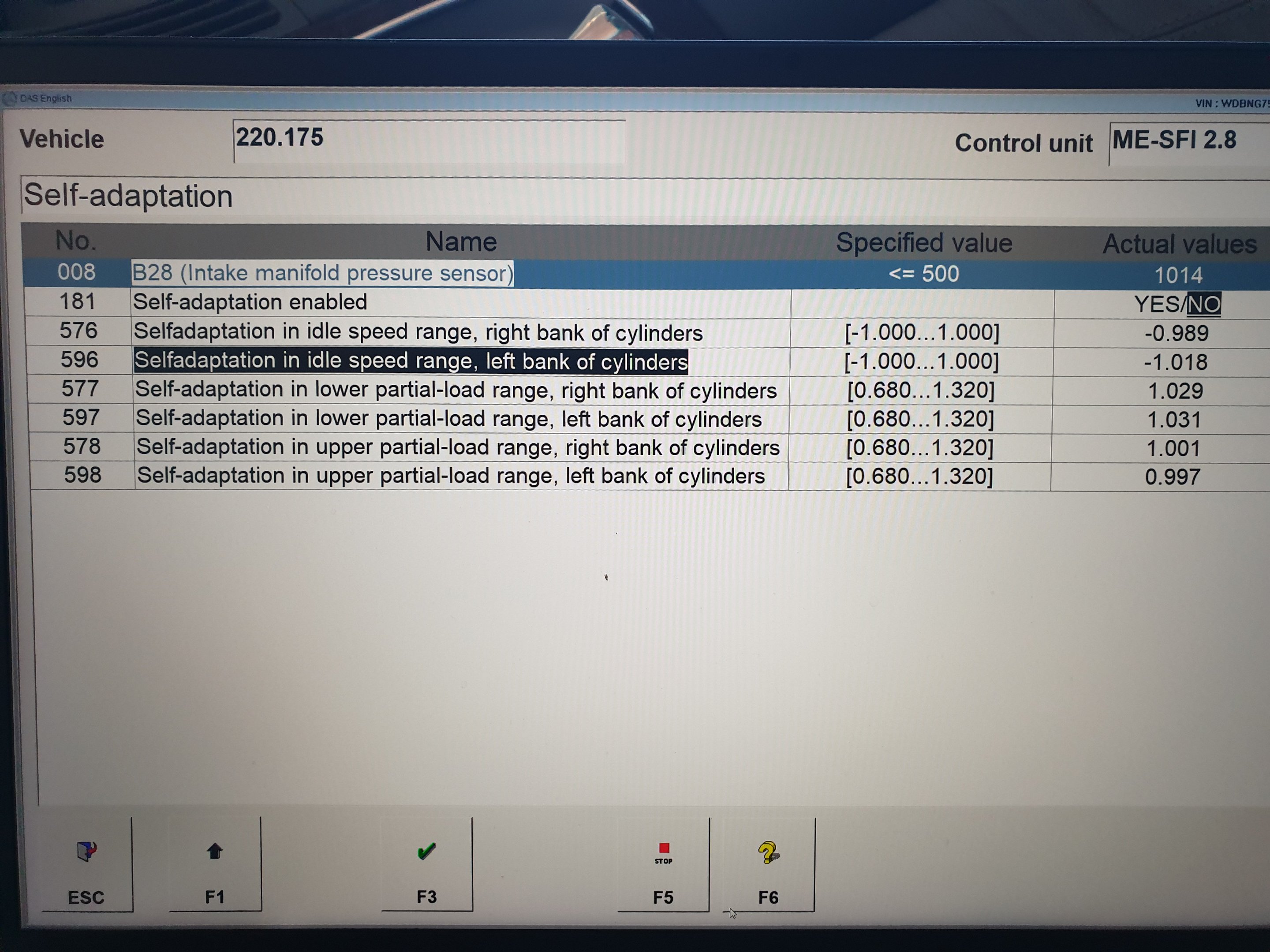
We see that the idle settled at 550 rpm immediately, with an ok intake vacuum. However, the calculated engine load is abnormal: a V8 should not idle at 24% load.
The air mass reading is also high: The expected value should be 16kg/h, which is 5g/sec, with 1g/sec/L being the rule of thumb for naturally aspirated engines over 2.5L.
Cleaning the MAF
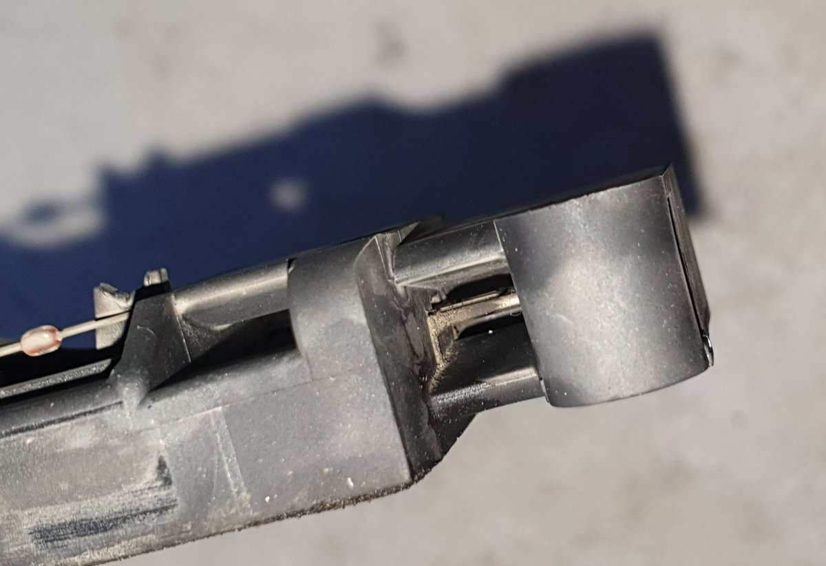
The MAf sensor uses two TTS25 pentalobe security screws to attach to the housing. Upon removal, it was immediately obvious that the sensor was extremely dirty, as you can see in the shot.
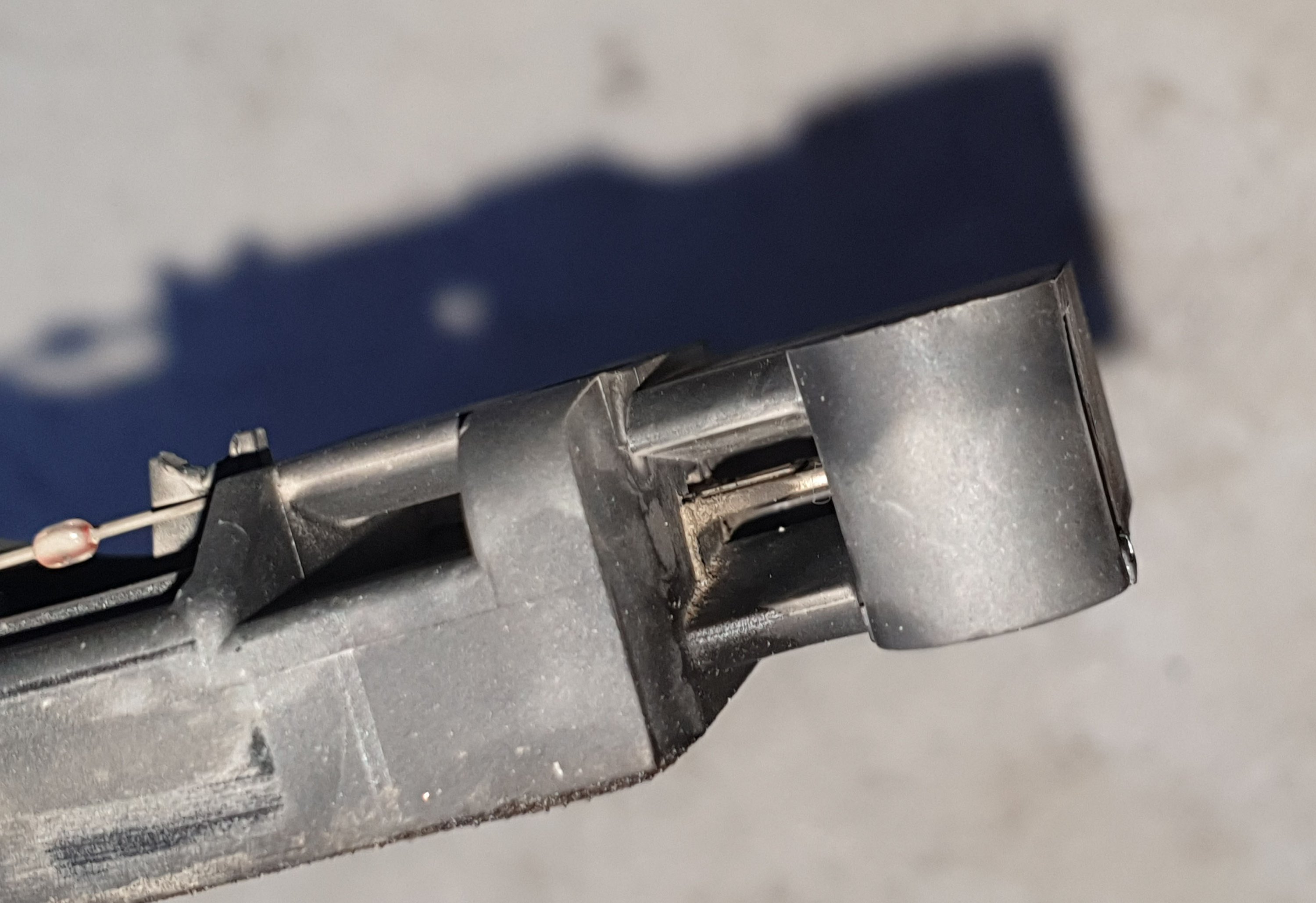
You can also see that on the outside there is a thermistor that measures intake air temperature. Inside the hole, there is the hot film sensor that measures air mass. This setup is common for MAF sensors in the last three decades.
I sprayed both with isopropyl alcohol generously and used cotton sticks to rubs them gently. I also pulled the cotton fibres partly off the sticks to clean the sides of the hot film.
Replacing vacuum hoses and intake gaskets
Before cleaning the MAF sensor, I replaced most vacuum hoses. There are just five of them on this engine:
a. One in the back for actuating the EGR valve. Blocking the vacuum port off would delete the EGR without the need for any blocking plate. It can be disabled in DAS.
b. Two in the front centre of the intake manifold, for the MAP sensor and for actuating the secondary air injection valves. Blocking the second one would delete the secondary air injection system.
c. One crossover hose connecting the two secondary air injection valves.
d. Finally, one in the front bottom of the intake manifold for the intake switchover valve. This hose is critical for top-end power, as it shortens the intake geometry when the engine revs above 3700rpm. Longer intake path gives higher velocity, which results in better fuel-air mixing and more torque. Shorter intake path prioritizes volume, which is more important for top-end power, especially important for a SOHC naturally aspirated engine with inherent air flow deficiencies like the M113.
I have replaced all but this last hose.
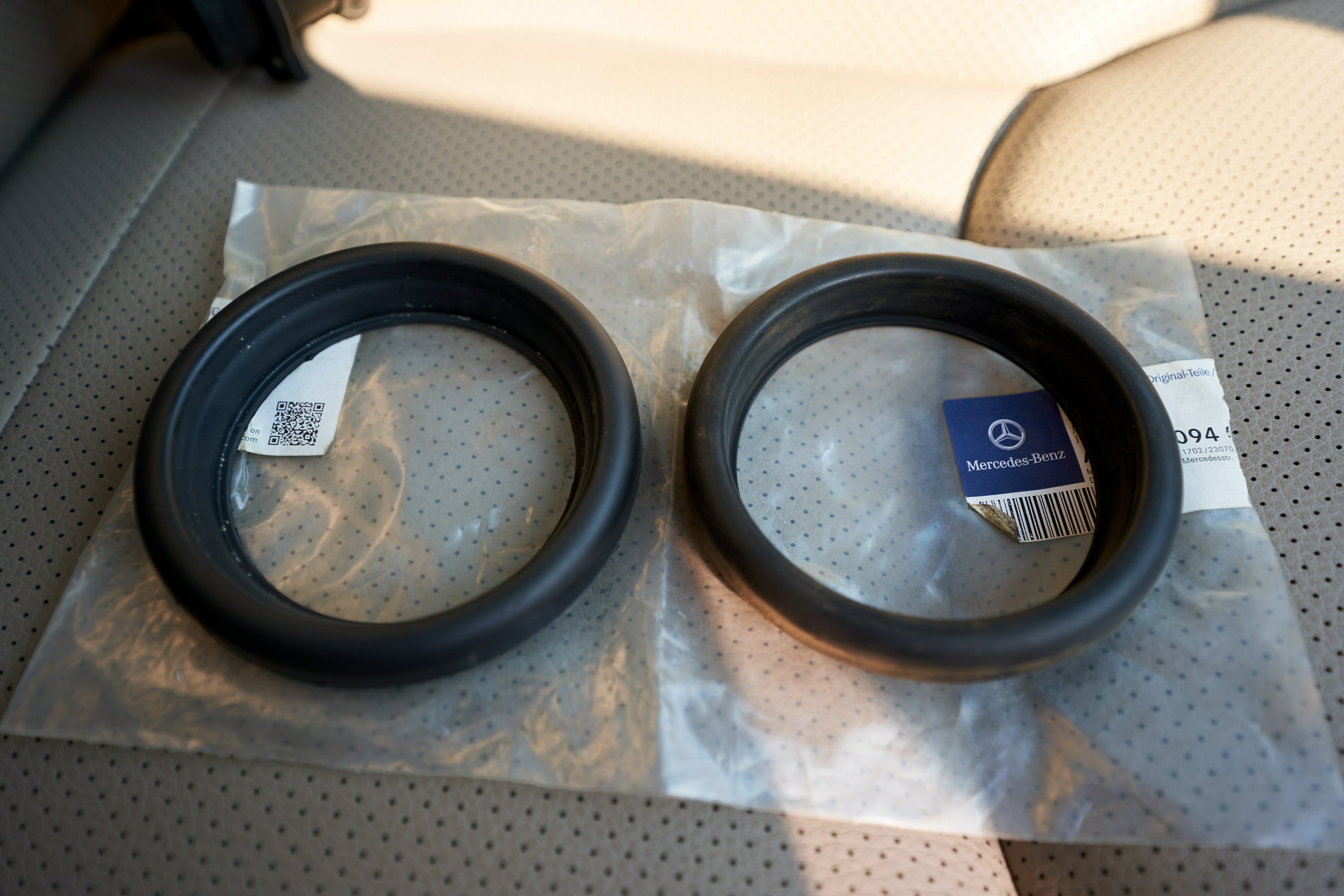
After cleaning the MAF sensor and seeing how dirty it was, I proceeded to replace the three seals up- and downstream the MAF. From the above picture, you can clearly see that the old seal between the air cleaner and the MAF housing was leaking dusty air in. The bottom-most seal was also very loose.
The new seals are MUCH tighter, requiring considerable force to seat properly.
After cleaning the MAF
After cleaning the MAF sensor, I reset the fuel mixture adaptation.
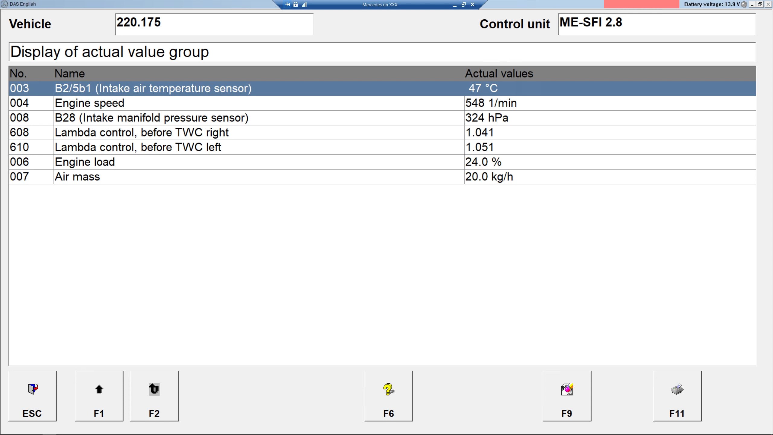
After running the car for about 50km, we can see the new readings here.
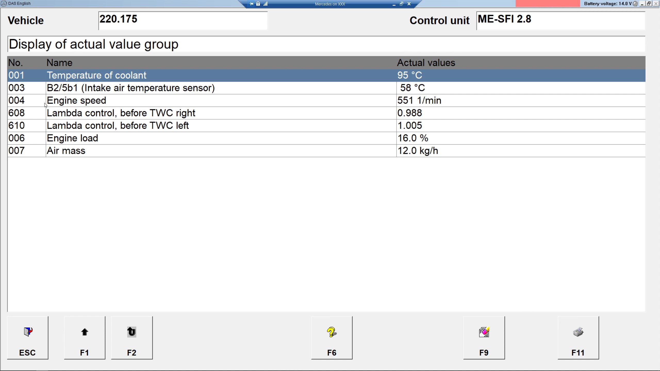
Now the engine load and air mass readings are lower. While the 12kg/h reading is on the low side, the 16% load is much closer to expectation.
A footnote here is that the calculated reading only displays in 4kg/h increments. This means it is closer to 12 than 16. The ‘.0’ is deceiving.
A reading lower than 16 is more or less ok, since Mercedes’s SOHC engines of this generation are known to have poorly flowing heads.
After another 100km drive, during which the engine felt more responsive than before, the transmission shifted better, and the fuel consumption dropped, let’s look at the LTFT.
We can see that the additive fuel trim stabilized at under 5% positive for both banks. The footnote here is that the injectors are expected to open roughly 3.2 to 4ms at idle.We also see that the multiplicative fuel trims were 2.7% and 2.2% positive for bank 1 and 2 respectively.
This is much better LTFT than the -25% at idle before cleaning.
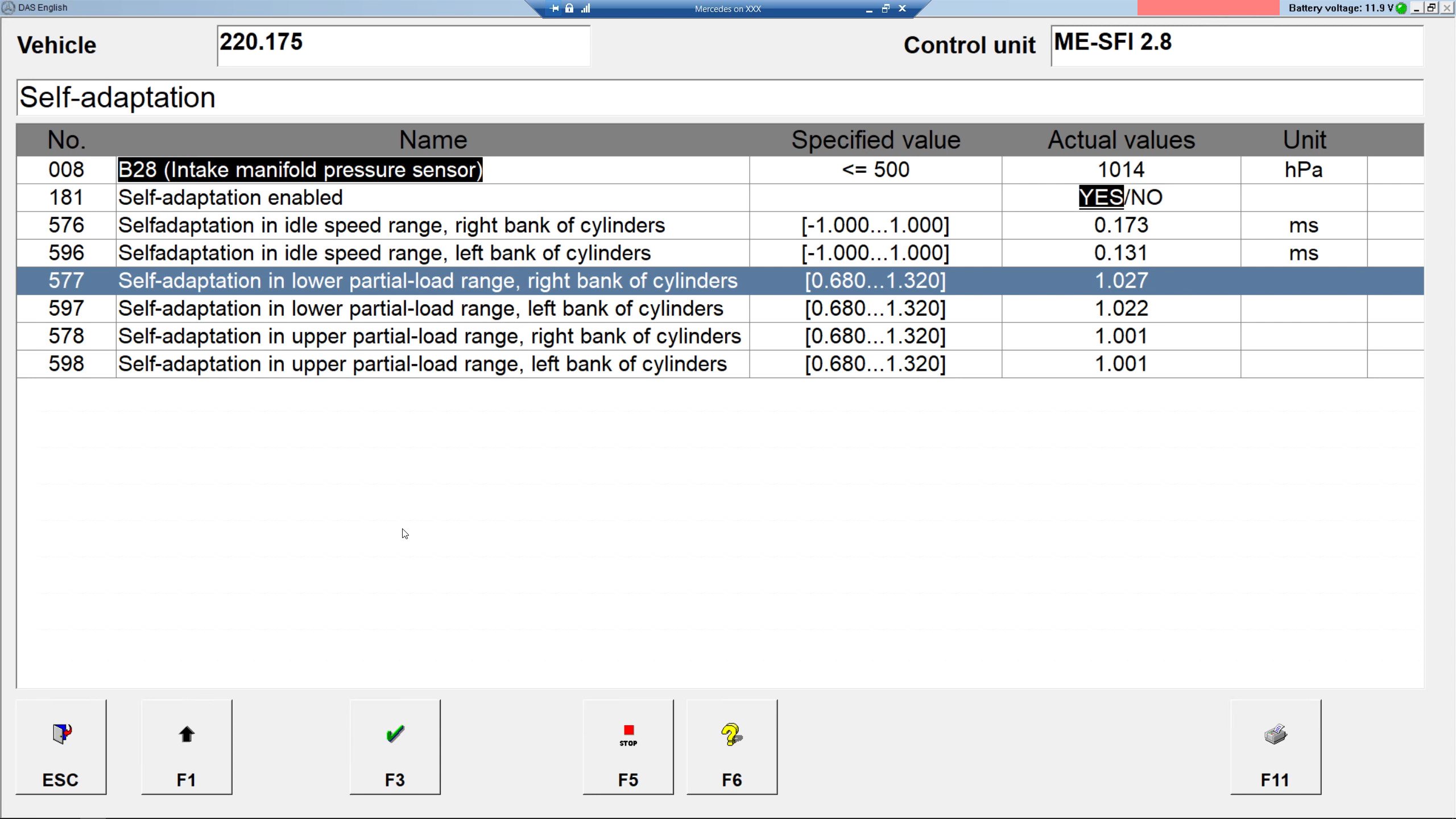
Also note that we have 10% ethanol in the fuel here. The stoichiometric AFR for ethanol is 9 to 1. If my calculation is correct, this means that the LTFT for an ECU tuned to run on 100% gasoline should be 3.43% positive.
The discrepancy between the two banks is likely caused by a slightly lazier oxygen sensor, though it may also be slightly out-of-balance injectors. I may try to clean the bank 1 sensor, which I know is slower, later.
Below uploaded to YT:

