techXXX
Designing the Cylinder Head for a 3L NA 11.5k-rpm V12—If I Had a Car Company 05
Previously, I have explained the reasoning behind the design of the bottom-end of the 3L naturally-aspirated V12 that I would build. Today, let us move on to the cylinder head.

Previously, I have explained the reasoning behind the design of the bottom-end of the 3L naturally-aspirated V12 that I would build. Today, let us move on to the cylinder head, specifically.
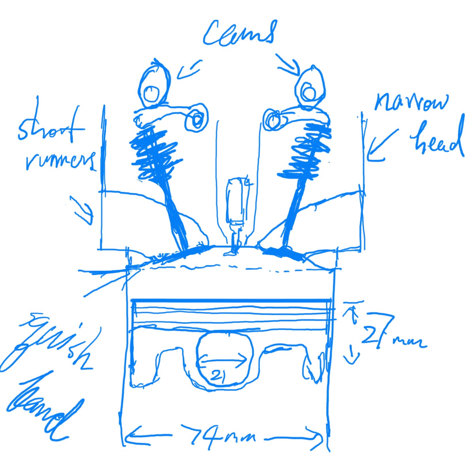
- Shallow combustion chamber: Small, 30% squish band, Central spark plug, 40° valve angle (20° per side) *need engineering
- Target compression ratio (CR): 13:1
- Combustion chamber volume: ~ 16.8cc
- Cams: DOHC (quad cam)
- Intake valve: Titanium, D 34mm, Lift 12.5mm, Duration 280° @ 1mm, Mass < 40g
- Exhaust valve: Titanium, D 29mm, Lift 11.5mm, Duration 265° @ 1mm, Mass < 35g
- Springs: Dual ovate-wire steel springs, Titanium retainers, Finger followers
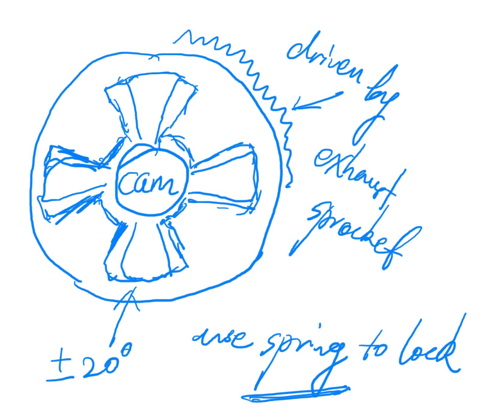
- Valve timing: VVT only for intake, +/-20°, Locked at high rpm / default to 30° overlap
- Valve overlap: 18° idle / cold, 45° full power, *need engineering, Only by adjusting intake cam
Combustion Chamber
Thanks to port injection, we can optimize the shape of the combustion chamber of our V12, because we do not need to account for the injector coming in from the side. The centrally-located spark plug at the dome will not compromise valve diameter or angle. Intake and exhaust runners can also be optimized.
Thanks to its small displacement, our V12 has a small bore at 74mm while having a high bore-to-stroke ratio. The flame travel distance is short, and burn is fast and stable. Together with natural aspiration, it enjoys high knock resistance. We just need to ensure that air can move fast to make power safely.
We want a strong squish that helps with fuel burn while leaving more room for valves to flow air. This is why I chose a 0.8mm deck clearance combined with a tight squish band. For those who are not aware, squish is an effect when parts of a piston come very close to the engine head, in what is known as a squish band. This creates turbulence of the air-fuel mixture near TDC.
At high RPM, pressure from compression ratio is less of a concern for power than combustion duration. Nevertheless, I specified a relatively high compression ratio of 13:1, because this is for a street-going vehicle.
Overall, we want the combustion chamber to be small and shallow with a gentle, continuous curvature. Valves should come in at a moderate angle, around 20° on either side. Our piston will have a flat crown with subtle valve reliefs.
Please note that the numbers here are only the starting point. Testing needs to be done before choosing the optimal valve angle and combustion chamber volume. The compression ratio will be affected as a result.

Valve and Spring
For a high-revving NA engine, a general rule is for the intake valve diameter to be up to 54% of bore, and for the exhaust valve diameter to be up to 85% of that of the intake. However, with a rather flat combustion chamber, there is no room for the valves to hit the upper end of this. Thankfully, it should not make much of a difference anyway, because valve mass also demands that we cannot go too large.
At high RPM, valve float becomes a major concern. For 11.5k RPM redline and occasionally over-speeding to 12k RPM, we can get away with steel springs if we are disciplined on valve mass and spring design. Of course, titanium valves are non-negotiable. Inconel valves, which can be even more expensive, are not needed nor desired, because our naturally-aspirated engine has cooler exhaust temperature and Inconel is heavier. Dual ovate-waire springs are needed. These have oval cross-sections that place more material in areas where it is needed.
If we were to build an exotic engine, titanium springs can add more headroom. On the other hand, if it is a 4L 9k-RPM V12, we can get away with a cheaper valvetrain.
Finger Follower
For our high-revving V12, finger follower makes the most sense. In comparison, bucket tappet is heavier, which increases the inertia in the valvetrain and is a no-no for high-RPM duty. Direct cam-on-bucket design also inherently comes with more cam lobe wear. This is exacerbated at high RPM.
Finger follower is in theory a type of lightweight rocker arm. However, while the standard rocker arm has a central pivot and is pushed from below by the cam, the finger follower has its pivot point at one end and is pushed down from above. There are two categories of finger followers, one with a hydraulic lifter and one without. We should go with the second type, which is lifter and stronger.
VVT
Variable valve timing is not strictly necessary, but practical so for our street-going, high-revving V12. We are not chasing fuel economy numbers or low-end torque, but we need the ability to adjust valve overlap to get top-end power and low-end smoothness. This is particularly salient with ITBs and high compression.
If we were to run a significant valve overlap at idle and low-RPM, with short effective intake runners and high compression, exhaust gas reversion and unstable air-fuel ratio will result. This leads to poor running and high emissions. However, if we were to run a low overlap at high-RPM, we will not be taking full advantage of the scavenging effect, resulting in a lower volumetric efficiency and thus lower output.
Nevertheless, we do not need extreme amount of adjustability found in certain German engines, because our small displacement, naturally-aspirated, port-injected engine with Nikasil coating is already fuel-efficient and knock-resistant. A small amount of VVT solely for the intake cams will suffice, with probably a 30° overlap as the default and 20° either way as the range.
Note that in my original specification I mentioned electric actuators. On second thought, this may be suboptimal for a high-revving engine. Conventional hydraulic VVT actuators will be more durable for high-RPM duty.
If this is a 4L 9k-RPM V12, I would do away with VVT altogether.
Intake and Exhaust Runners
Another crucial aspect of the head design is that of the intake and exhaust runners. I will cover them together with the intake and exhaust systems in the next post.