techXXX
Designing the Intake and Exhaust for a 3L NA 11.5k-rpm V12—If I Had a Car Company 06
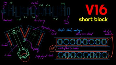
Previously, I have discussed the design of the long block of the 3L naturally-aspirated V12 that I would build. Today, let us delve into the intake and exhaust systems.
Previously, I have discussed the design of the long block of the 3L naturally-aspirated V12 that I would build. Today, let us delve into the intake and exhaust systems, including:
- Air intake: ITBs (individual throttle bodies), Short total intake runner length ~ 3” *need engineering
- Airbox: 10.5L airbox directly on top of ITBs
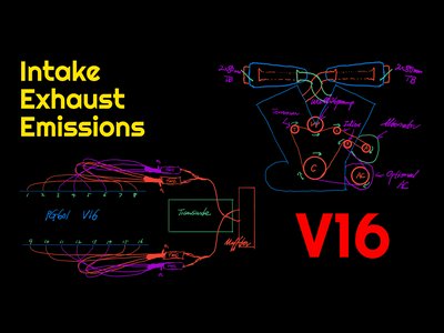
- Equal-length exhaust headers: 6–2–1
Intake Runner
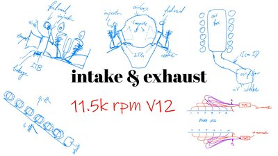
Our small-displacement, high-revving V12 should optimally be paired with moderately-sized, very short intake runners. Specifically, the ideal intake runner size is 4cm in diameter and 15–20cm in length. Note that the length is from the tip of the trumpet inside the airbox to the intake valve.
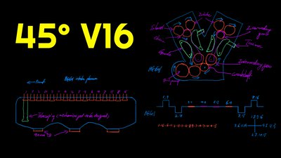
In the cylinder head, this requires an immediate, though smooth turn to the side, as my drawing illustrates. While a straight shot is better in isolation, it matters much less than diameter and length. This setup also favors a narrow engine head. Fortunately, it is possible for a small displacement, naturally-aspirated, port-injected engine using Nikasil-coated block and finger followers.
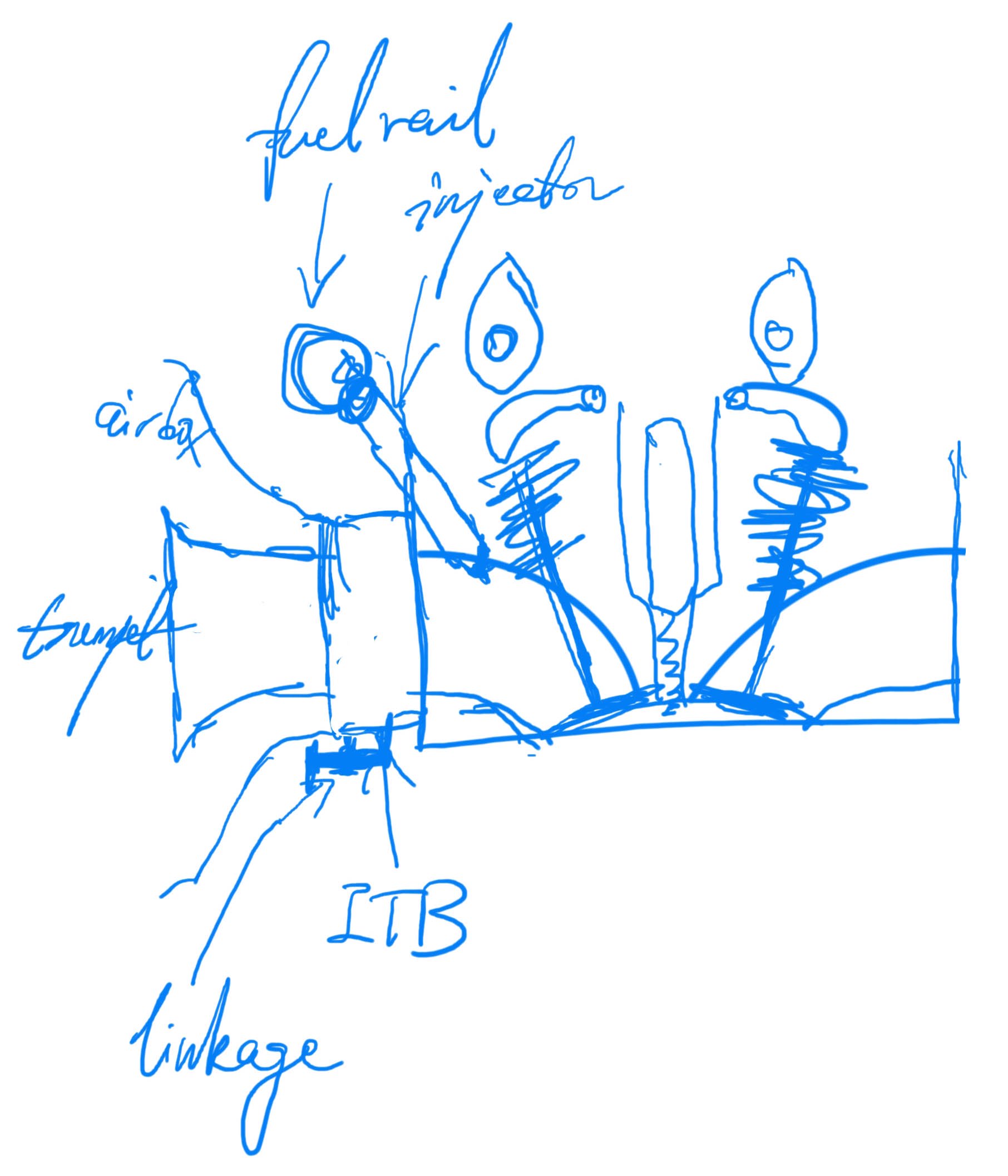
Individual Throttle Bodies
For fast response and short intake runner length, ITBs are the best. We will use 4cm-diameter ITBs with remote actuators. That is, the throttle bodies on each cylinder bank are linked mechanically, and a single actuator operates all six butterfly valves together. This ensures that all ITBs are in sync and balanced. It also allows the throttle bodies to be made much thinner in depth, perhaps down to just 2cm, but not more than 3cm. This would allow us to keep the intake runner short.

Airbox and Air Intake
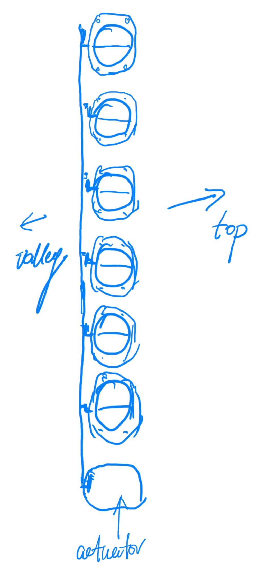
A large airbox rides directly above the ITBs. There are individual trumpets inside the airbox for each cylinder. These trumpets make up part of the take runner; their shape should be tuned for 11k RPM. The volume of the airbox should be at least 4x the engine’s displacement, at 12L.
Feeding this airbox should be one or two cold air intakes at the very front of the vehicle. Since our intake runners are 4cm each in diameter, the intake piping should be 15cm or 6in if we use one or 10cm or 4in if we use two. Air filter or filters should be between the cold air intake and the main airbox.
Note that with ITBs, this engine does not have an intake manifold. The injectors should go directly onto the engine head.
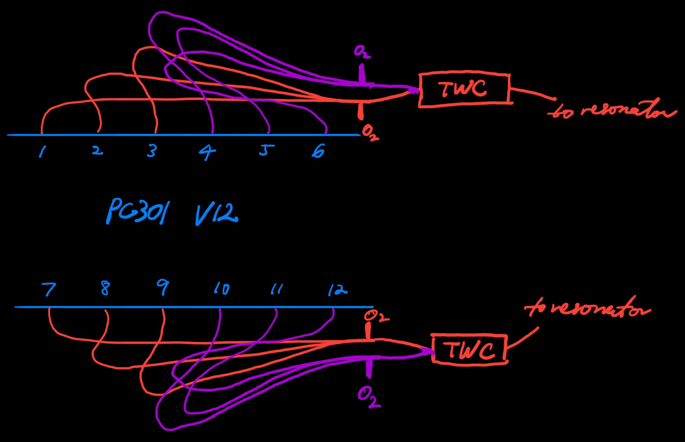
Equal-Length Exhaust Header
Our V12 will use equal-length exhaust headers in a 6–2–1 setup. That is, Cylinders 1, 2, and 3 will merge first before joining 4, 5, and 6 in the second merge. Like the intake, exhaust diameter and length also matter for power output. The individual pipes directly coming out the cylinder head should be 4cm in diameter. After the first merge, it should be stepped up to 7cm. After the final merge, the exhaust pipe should have an internal diameter of 10cm or 4in. All merges should be at small angles with no sharp edges. The 7cm section should be reasonably long. Obviously, the exact setup must be tuned with the real engine running under load, or at least verified with simulation.
We should use two lambda sensors per bank, placed 20cm after the first merge. This would allow us to monitor and control the combustion more precisely.
Exhaust Setup
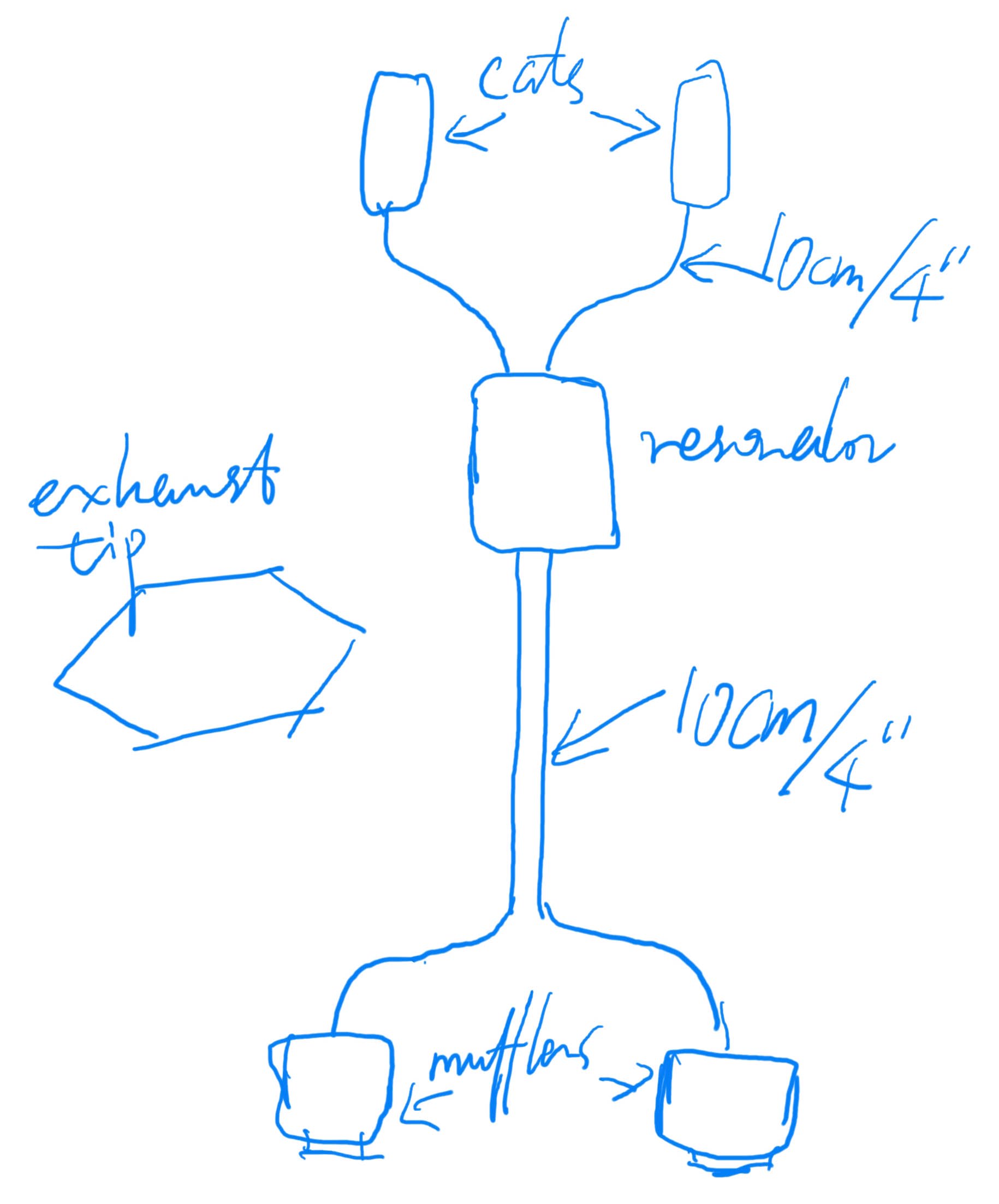
Beyond the exhaust headers, the full exhaust setup is crucial not only for sound but also for power. Ideally, for our engine the total exhaust length should be between 1.5m and 2m. Unfortunately, ours is not a rear- or mid-engine vehicle, and side exhausts come with numerous practical downsides. Therefore, we accept that exhaust scavenging is out of the picture and focus instead on minimizing backpressure.
Hence, we put a large resonator downstream of the catalytic converters. The two 10cm pipes from both cylinder banks come in one side, and two 10cm pipes go out the other side towards the rear of the vehicle. A high-flow muffler should be installed at the rear for each side. We will use one large hexagonal exhaust tip for each muffler to represent the V12 engine.
Up Next
In the next post, I will round out the engine design with fuelling, cooling, and accessories.